Zirka PB Nano - Arduino compatible board in nano form factor, based on the improved RISC AVR 8-bit ATmega328PB microcontroller. The ATmega328PB is backward compatible with the ATmega328 and is not a complete replacement for the latter. Code developed for ATmega328 will work correctly on ATmega328PB.
ATmega328PB specifications:
Flash: 32 KB
EEPROM: 1 KB
SRAM: 2 KB
8-bit Timer/Counters: 1
16-bit Timer/Counters: 3
PWM Channels: 10
8-channel 10-bit ADC
USART: 2
SPI: 2
I2C: 2
Programmable Watchdog Timer
On-Chip Analog Comparator
Internal 8 MHz Calibrated Oscillator
Clock Failure Detection Mechanism and Switch to Internal 8 MHz RC Oscillator in case of Failure
Individual Serial Number to Represent a Unique ID
27 Programmable I/O Lines
Built-in temperature sensor
The ATmega328PB supports hardware touch scanning using a Peripheral Touch Controller (PTC)
Six Sleep Modes: Idle, ADC Noise Reduction, Power-save, Power-down, Standby and Extended Standby
Operating Voltage: 1.8 - 5.5V
DC Current per I/O Pin 40.0 mA
DC Current VCC and GND Pins 100.0 mA
Technical characteristics of the board:
Board size: 49 x 20 mm
Analog input: A0 - A7
PWM: 10
Pins SDA1(PE0) and SCL1(PE1) can be used as general purpose I/O pins
There are two LEDs on the board: blue - power supply, red on pin 13.
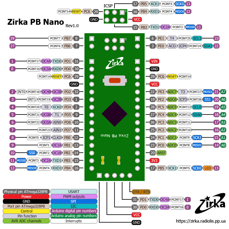
Connectors:
On one side there is a 5-pin connector for serial programming (the bootloader must be loaded into the board first). Any UART-USB converter can be used for serial programming, such as CP2102, CH340G, PL2303HX or others.
On the other side is the 6-pin ICSP connector for in-circuit programming.
The board is available in two versions: 5V and 3.3V.
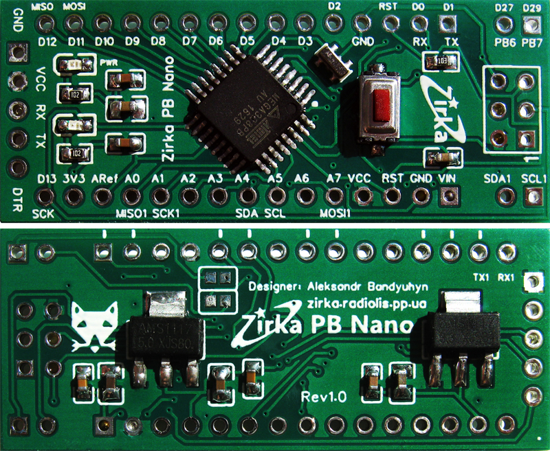
Board version 5V. The 5V board has a 16MHz external resonator.
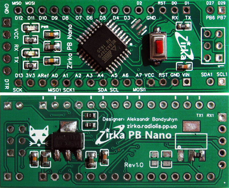
Board version 3,3V. The 3.3V board uses an 8 MHz internal resonator. On a 3.3V board, pins PB6 and PB7 can be used as digital pins.
Power supply
Voltage up to 12V can be connected to the board through the VIN contact. In this case, the voltage will be regulated by the built-in regulator, depending on the board version (5 or 3.3V).
Through the VCC contact, you can connect strictly the voltage for which the board is designed (5 or 3.3V). Applying a higher voltage through the VCC contact can damage the microcontroller. This pin is involved in the power supply of the board when it is connected to a computer via a UART-USB converter.
Voltage can be supplied from the VCC contact to sensors and modules. Current consumption must not exceed 800 mA.
For a voltage of 3.3V, a linear stabilizer AMS1117 is used, with a maximum current of up to 800 mA, which allows you to connect more powerful modules, for example, NRF24L01.
Patch for Arduino IDE 1.8.x
The patch and boards are tested.